
Bolt Circle Coordinates: Drilling Holes on a Pitch Circle
The trigonometry behind bolt hole patterns, angle conventions, chord spacing, partial arcs, measuring wheel bolt patterns and laying out flanges on a manual mill or CNC.
By Redbison Dev · · Updated · 9 min read

Flanges, wheel hubs, motor adapters, encoder discs and pipe fittings all share one feature: a ring of holes evenly spaced on a circle. Machinists call it a bolt circle; drawings call its diameter the PCD (pitch circle diameter) or BCD. Drilling one accurately without a rotary table comes down to a short piece of trigonometry. This guide covers the formulas, the angle conventions that trip people up, partial patterns, hole spacing, measuring an unknown pattern, and practical tips for the mill. The Bolt Circle Calculator produces the coordinate table and a CSV.
The coordinate formula
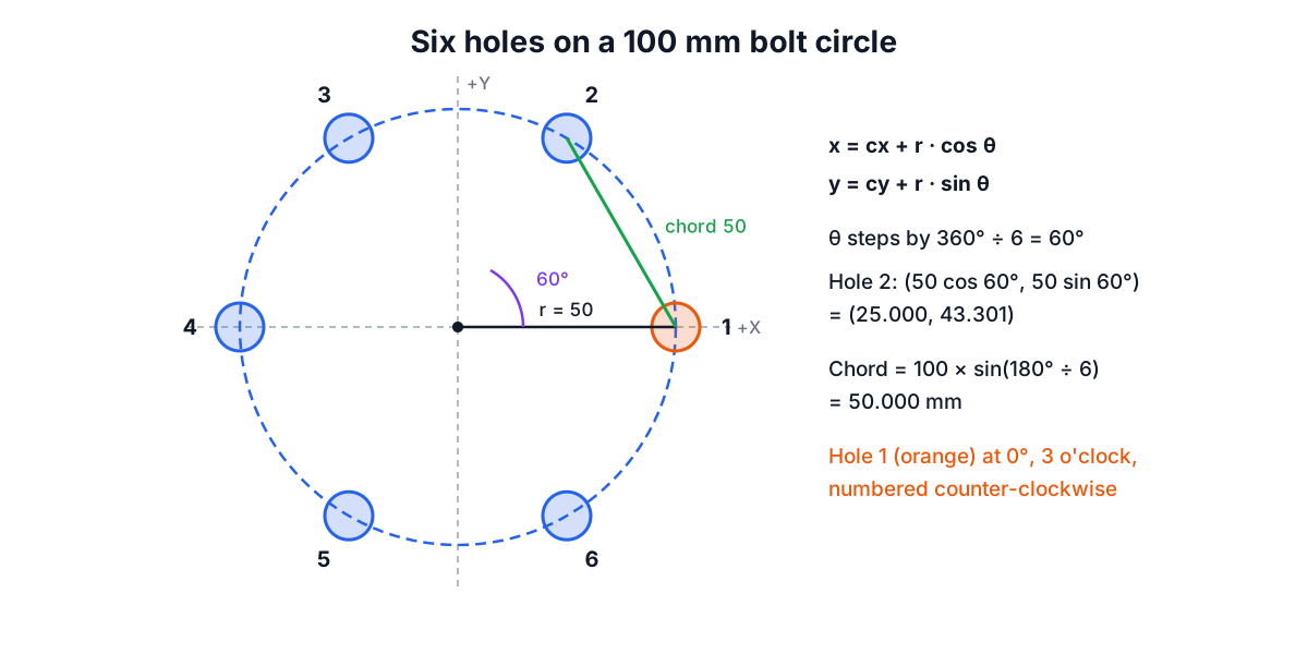
Put the circle's centre at (cx, cy) and call its radius r = PCD ÷ 2. A hole at angle θ, measured counter-clockwise from the positive X axis, sits at:
x = cx + r · cos θ y = cy + r · sin θ
For N holes on a full circle, the angle between neighbours is 360° ÷ N, so hole k (counting from 0) is at θ = θ₀ + k × 360° ÷ N, where θ₀ is the angle of the first hole.
Six holes on a 100 mm PCD, first hole at 0°:
| Hole | Angle | X | Y |
|---|---|---|---|
| 1 | 0° | 50.000 | 0.000 |
| 2 | 60° | 25.000 | 43.301 |
| 3 | 120° | −25.000 | 43.301 |
| 4 | 180° | −50.000 | 0.000 |
| 5 | 240° | −25.000 | −43.301 |
| 6 | 300° | 25.000 | −43.301 |
The 43.301 is 50 × sin 60° = 50 × 0.866025. Keep at least three decimals in millimetres or four in inches when drilling; rounding sin 60° to 0.87 puts holes 0.15 mm out on this small circle and more on a large one.
Angle conventions
Mathematics and most CAD systems measure angles counter-clockwise from 3 o'clock (the +X axis). Many drawings, wheel specifications and machinists instead start at 12 o'clock and count clockwise, like a clock face. Neither is wrong, but mixing them mirrors or rotates the pattern.
To convert a clockwise-from-12 angle α into the mathematical angle: θ = 90° − α. A hole at "2 o'clock" (α = 60°) is at θ = 30°. The calculator accepts either reference and either direction, and its preview highlights hole 1 so you can see which way the numbering runs.
Also watch the machine's own axes. On most vertical mills, +X moves the tool right relative to the work and +Y moves it away from the operator, which matches a drawing seen from above. Some DRO setups or lathes with live tooling differ; if your first two holes come out mirrored, flip the sign of Y.
Hole spacing: the chord
The straight-line distance between two neighbouring holes is the chord of the circle:
c = PCD × sin(180° ÷ N)
| Holes | Chord as fraction of PCD | On 100 mm PCD |
|---|---|---|
| 3 | 0.8660 | 86.603 |
| 4 | 0.7071 | 70.711 |
| 5 | 0.5878 | 58.779 |
| 6 | 0.5000 | 50.000 |
| 8 | 0.3827 | 38.268 |
| 12 | 0.2588 | 25.882 |
Six holes give a chord exactly equal to the radius, the property behind laying out a hexagon with a compass. The chord is the most useful check in the shop: after drilling the first two holes, measure between them with calipers (over the holes minus one hole diameter, or with pins). A wrong PCD or a wrong angle shows up immediately.
More generally, holes k positions apart are PCD × sin(k × 180° ÷ N) apart. With an even number of holes, the two opposite holes (k = N ÷ 2) are exactly one PCD apart.
Partial bolt circles
Some parts have holes over an arc only: a segment of a flange, a slotted adjustment plate, a sector gear. Here the spacing is set by the included angle A from the first hole to the last:
pitch = A ÷ (N − 1)
Note the N − 1: three holes over 90° sit at 0°, 45° and 90°, with the first and last on the ends of the arc. A full circle is different because the last hole does not land back on the first, so it uses 360° ÷ N. Enter the included angle in the calculator to switch to a partial pattern.
Offsets and datums
Drawings rarely put the origin at the circle centre. A flange might be dimensioned from its bottom-left corner with the bolt circle centred at (50, −30). Add the centre coordinates to every hole, as the formula does. For an 8-hole pattern on 200 mm PCD starting at 22.5° and centred at (50, −30), hole 1 is at (50 + 100 cos 22.5°, −30 + 100 sin 22.5°) = (142.388, 8.268). Starting at half the pitch angle (22.5° for 8 holes) is common on pipe flanges, so that no hole sits on the vertical or horizontal centreline; ASME B16.5 flanges, for example, straddle the centrelines.
Measuring an unknown pattern
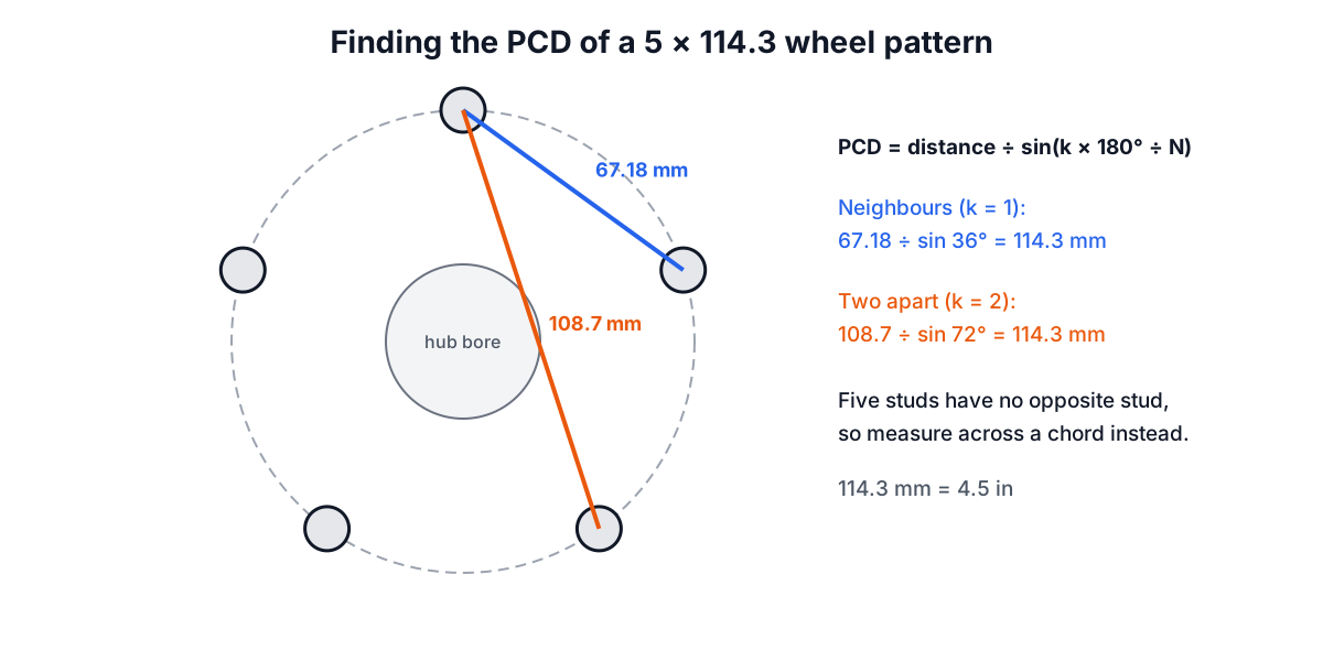
To find the PCD of an existing part, measure between hole centres and invert the chord formula:
PCD = distance ÷ sin(k × 180° ÷ N)
For an even number of holes, measure across opposite holes: that distance is the PCD. For an odd number there is no opposite hole. On a five-lug wheel, measure centre to centre between neighbouring studs and divide by sin 36° = 0.5878: 67.18 mm gives 114.3 mm, the common 5 × 114.3 (5 × 4.5 in) pattern. Measuring studs two apart (k = 2) gives a longer, more accurate reading: 114.3 × sin 72° = 108.7 mm.
Measuring centre to centre is easiest with the hole edges: measure from the inside edge of one hole to the outside edge of the other, which equals the centre distance when both holes are the same size.
Drilling a bolt circle on a manual mill
- Find the circle centre with an edge finder or indicator and zero the DRO there (or at the drawing datum, and enter the centre as an offset).
- Spot drill every hole from the coordinate table first; spot drills do not wander and you can check the pattern before committing.
- Check the chord between two spotted holes against the table.
- Drill and ream or bore to size, approaching every position from the same direction to take up backlash on a machine without a DRO.
Many DROs and CNC controls have a built-in bolt hole circle function. It is still worth comparing its first two positions with a table, because a start angle or direction setting different from the drawing's convention is the commonest error.
When coordinates are not enough
For very large circles, tolerance on hole position matters more than the coordinate arithmetic: thermal growth of the part and machine, and the accuracy of the axes over long travels. Position tolerances on drawings are usually given with geometric tolerancing (a true position callout), which allows a circular zone around each theoretical position. When two parts must bolt together, the hole clearance and the position tolerance of both parts together decide whether the bolts will pass; the floating fastener formula T = H − F (the position tolerance on each part equals the minimum clearance hole size minus the fastener size) is the usual check.
Related reading: ISO 286 Fits and Tolerances for the bores those holes may need, and the Tap Drill Calculator for threaded holes. The Speeds and Feeds Calculator gives spindle speed for the drill.
Frequently asked questions
What are the coordinates for 6 holes on a 100 mm PCD?
With the first hole at 0° and the centre at the origin, six holes on a 100 mm pitch circle sit at (50, 0), (25, 43.301), (−25, 43.301), (−50, 0), (−25, −43.301) and (25, −43.301), spaced 60° apart. The 43.301 is 50 × sin 60°; keep at least three decimals in millimetres when drilling.
How do I convert a clock-face angle to a bolt circle angle?
Mathematics and most CAD systems measure angles counter-clockwise from 3 o'clock, while many drawings count clockwise from 12 o'clock. To convert a clockwise-from-12 angle α into the mathematical angle, use θ = 90° − α. A hole at 2 o'clock, α = 60°, is at θ = 30°. Mixing conventions mirrors or rotates the pattern.
Why do pipe flange bolt holes straddle the centreline?
Pipe flanges commonly start the first bolt hole at half the pitch angle, such as 22.5° for 8 holes, so that no hole sits on the vertical or horizontal centreline. ASME B16.5 flanges, for example, straddle the centrelines. Add the circle's centre coordinates to every hole when the drawing datum is elsewhere.
How do I check a bolt circle after drilling the first holes?
Measure the chord between two neighbouring holes and compare it with PCD × sin(180° ÷ N). Six holes on 100 mm should be 50 mm apart. Spot drill every hole first, since spot drills do not wander, then check the chord; a wrong PCD or angle shows up immediately.
What is the floating fastener formula?
The floating fastener formula, T = H − F, from ASME Y14.5, sets the position tolerance on each part equal to the minimum clearance hole size minus the fastener size. It is the usual check for whether bolts will pass through two parts that bolt together, since hole clearance and position tolerance on both parts together decide the fit.
Sources and further reading
- Polar Coordinates, Wolfram MathWorld.
- Chord, Wolfram MathWorld.
- Y14.5 Dimensioning and Tolerancing, ASME. Position tolerances for hole patterns.
- Standard plane trigonometry: polar to Cartesian conversion and the chord length formula.
- ASME B16.5, Pipe Flanges and Flanged Fittings, for flange bolt circle layouts.
Open the Bolt Circle Calculator
More Mechanical
Every tool in the Mechanical section, free and in your browser.
- Torque and Power Calculator
- Gear Ratio Calculator
- Pulley and Belt Calculator
- Bolt Torque Calculator
- Spring Calculator
- Stress and Strain Calculator
- Bearing Life Calculator
- Hydraulic Cylinder Calculator
- Tap Drill Size Calculator
- Speeds and Feeds Calculator
- ISO Fits & Tolerances Calculator
- Bolt Circle Calculator
- Shaft Torsion Calculator
- Shaft Diameter Calculator
- Shaft Key Size Calculator