
Reynolds Number Explained: Laminar, Transitional and Turbulent Flow
What Re = ρvD/μ measures, where the 2300 and 4000 limits come from, how temperature changes viscosity, and how to use hydraulic diameter for ducts and annuli.
By Redbison Dev · · Updated · 10 min read

Before you can calculate friction in a pipe, heat transfer in a tube or drag on a body, you need to know what kind of flow you have. Smooth, layered laminar flow and chaotic turbulent flow follow different laws, and the switch between them is governed by one dimensionless number. This guide explains the Reynolds number used by the Reynolds Number Calculator: what it compares, where the familiar 2300 and 4000 limits come from and how firm they are, how strongly temperature moves it, and how to apply it to ducts and annuli with the hydraulic diameter.
What the Reynolds number compares
The Reynolds number is the ratio of inertial forces, which keep a disturbance moving, to viscous forces, which damp it out:
Re = ρ v D / μ = v D / ν
- ρ is density (kg/m³)
- v is mean velocity (m/s)
- D is a characteristic length, the inside diameter for a round pipe (m)
- μ is dynamic viscosity (Pa·s), and ν = μ/ρ is kinematic viscosity (m²/s)
Every unit cancels, so Re is a pure number. That is its power: a 50 mm water pipe and a 5 mm oil capillary at the same Re have the same flow pattern, which is why scale models and correlations work. When viscous forces win (low Re) small eddies die out and the fluid slides in layers. When inertia wins (high Re) eddies grow and the flow mixes.
Osborne Reynolds showed this in 1883 by injecting a thin stream of dye into water flowing through a glass tube. At low speed the dye stayed a sharp line. Above a certain speed it wavered, then broke up and filled the tube.
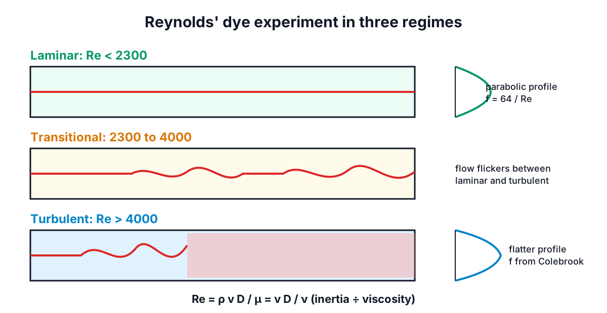
The 2300 and 4000 limits
For flow in round pipes, engineers conventionally use:
| Re | Regime | Friction factor |
|---|---|---|
| below about 2300 | Laminar | f = 64/Re exactly |
| 2300 to 4000 | Transitional | Unpredictable, avoid |
| above about 4000 | Turbulent | Colebrook / Moody chart |
These are conventions, not constants of nature. Some texts set the laminar limit at 2000 or 2100. Reynolds himself kept flow laminar to around 12,000 by letting the water settle in the tank and using a smooth entrance, and later experimenters have reached far higher values with extreme care. Real systems, with pumps, elbows, vibration and rough entrances, usually go turbulent close to the conventional value. The transition band is a zone where flow can flicker between the two states ("puffs" and "slugs"), so pressure drop and heat transfer jump about. Good practice is to design clear of it.
Other geometries have different critical values. Flow along a flat plate, measured from the leading edge, typically stays laminar up to Re around 5 × 10⁵. Flow around a sphere or cylinder has a series of regimes defined by Re based on diameter. Stirred tanks use an impeller Reynolds number. Do not carry the pipe numbers over to those cases.
Viscosity and temperature: the input that moves most
Velocity and diameter are usually known within a few percent. Viscosity is where big errors come from, because it is very sensitive to temperature in liquids. Water values used by the calculator (CRC Handbook densities, IAPWS viscosities):
| Temperature | Density (kg/m³) | Viscosity (mPa·s) | ν (mm²/s) |
|---|---|---|---|
| 0 °C | 999.84 | 1.791 | 1.792 |
| 10 °C | 999.70 | 1.306 | 1.306 |
| 20 °C | 998.21 | 1.002 | 1.003 |
| 40 °C | 992.22 | 0.653 | 0.658 |
| 60 °C | 983.20 | 0.466 | 0.474 |
| 80 °C | 971.79 | 0.354 | 0.364 |
| 100 °C | 958.35 | 0.282 | 0.294 |
The same 50 mm pipe at 1 m/s gives Re = 38,270 at 10 °C and Re = 105,500 at 60 °C. Both are turbulent, but the friction factor and heat transfer coefficient differ.
Oils change far more. ISO 3448 viscosity grades are named after their kinematic viscosity at 40 °C, so ISO VG 32 is 32 cSt at 40 °C. The same oil may be several hundred cSt on a cold morning and under 10 cSt at 100 °C. A hydraulic line that runs at Re = 1,563 when warm (VG 32, 25 mm bore, 2 m/s) could be at Re below 200 when cold, with eight times the friction.
Gases go the other way: their viscosity rises with temperature, and their density falls, so Re for a given velocity drops as a gas heats up. Air at 20 °C and 1 atm has ρ = 1.204 kg/m³ and μ ≈ 1.81 × 10⁻⁵ Pa·s, a kinematic viscosity about 15 times that of water.
Keep dynamic and kinematic viscosity straight. Centipoise (cP = mPa·s) is dynamic; centistokes (cSt = mm²/s) is kinematic. They are equal only when the density is 1000 kg/m³. For an oil at 860 kg/m³, 32 cSt is 27.5 cP.
Hydraulic diameter for non-round sections
For ducts, annuli and other shapes, replace D with the hydraulic diameter:
Dh = 4A / P
where A is the flow area and P the wetted perimeter. Useful cases:
- Round pipe: Dh = D.
- Rectangle a × b: Dh = 2ab / (a + b). A 400 × 200 mm duct has Dh = 266.7 mm.
- Square: Dh = side length.
- Annulus between pipes: Dh = D_outer − d_inner, which is twice the gap.
Air at 5 m/s in that 400 × 200 duct gives Re ≈ 88,700. Using the width would overstate it by 50%, using the height understate it by 25%. Turbulent friction correlations work reasonably well with Dh. Laminar friction does not quite: in a rectangle the laminar friction factor depends on aspect ratio and is not exactly 64/Re (it is about 57/Re for a square and approaches 96/Re for very wide slots). Treat laminar results in odd shapes as estimates.
Entrance length
Right after an entrance the velocity profile is still developing, so friction and heat transfer are higher than the fully developed values. Common estimates for the development length are L ≈ 0.06 Re D in laminar flow and L ≈ 4.4 Re^(1/6) D in turbulent flow. Turbulent flow develops within roughly 20 to 40 diameters; laminar flow can need hundreds. Short laminar heat-exchanger tubes may never be fully developed, which is why their correlations include L/D.
Worked example
Water at 20 °C flows at 2 L/s through a 50 mm bore.
- Velocity: v = Q/A = 0.002 / (π × 0.05² / 4) = 1.019 m/s.
- Properties: ρ = 998.2 kg/m³, μ = 0.0010016 Pa·s.
- Re = 998.2 × 1.019 × 0.05 / 0.0010016 = 50,760, turbulent.
- Velocity for Re = 2300: v = 2300 × ν / D = 2300 × 1.003 × 10⁻⁶ / 0.05 = 0.046 m/s.
To keep this pipe laminar you would need less than one twentieth of the flow. Practically every water pipe in a building or plant runs turbulent, while thick oils, blood in small vessels, microfluidics and slow seepage run laminar.
Common mistakes and limits
- Mixing cP and cSt without density. Check which one a data sheet means.
- Using the wrong temperature. Take viscosity at the operating temperature, and for heat exchangers at the bulk mean temperature.
- Using radius instead of diameter. Some open-channel texts define Re with hydraulic radius (A/P), which is a quarter of Dh; the critical values change accordingly.
- Treating 2300 as a hard line. It is a convention for round pipes with ordinary disturbances.
- Non-Newtonian fluids such as slurries, paints and polymer melts need a generalised Reynolds number based on their rheology.
Once you know the regime, the next step is usually friction. The Pipe Pressure Drop Calculator uses the same fluid presets and switches between 64/Re and Colebrook for you; the Darcy-Weisbach and Colebrook guide explains how. For velocities from a flow rate, see the flow rate guide.
Frequently asked questions
Who discovered the Reynolds number?
Osborne Reynolds showed the effect in 1883 by injecting a thin stream of dye into water flowing through a glass tube. At low speed the dye stayed a sharp line, and above a certain speed it wavered, then broke up and filled the tube. By letting the water settle and using a smooth entrance, he kept flow laminar to around 12,000.
What is the critical Reynolds number for flow over a flat plate?
Flow along a flat plate, with the Reynolds number measured from the leading edge, typically stays laminar up to about 5 × 10⁵, far above the 2300 used for round pipes. Spheres, cylinders and stirred tanks have their own regimes and Reynolds number definitions, so the pipe limits should not be carried over to them.
How do I convert centistokes to centipoise?
Centistokes measure kinematic viscosity and centipoise dynamic viscosity, and they are linked by density, because kinematic viscosity is dynamic viscosity divided by density. The two numbers are equal only when the density is 1000 kg/m³. For an oil at 860 kg/m³, 32 cSt is 27.5 cP.
What is the entrance length in pipe flow?
Entrance length is the distance after a pipe entrance over which the velocity profile develops, with friction and heat transfer higher than fully developed values. Common estimates are L ≈ 0.06 Re D for laminar flow and L ≈ 4.4 Re^(1/6) D for turbulent flow. Turbulent flow develops within roughly 20 to 40 diameters, while laminar flow can need hundreds.
Is water flow in a pipe usually laminar or turbulent?
Almost always turbulent. Water at 20 °C flowing at 2 L/s through a 50 mm bore has a Reynolds number of about 50,760, and keeping it below 2300 would need a velocity of only 0.046 m/s, less than one twentieth of that flow. Thick oils, blood in small vessels, microfluidics and slow seepage are the usual laminar cases.
Sources and further reading
- An experimental investigation of the circumstances which determine whether the motion of water shall be direct or sinuous, and of the law of resistance in parallel channels, Philosophical Transactions of the Royal Society of London. Osborne Reynolds' 1883 dye experiments.
- The Onset of Turbulence in Pipe Flow, Science. Avila and colleagues, 2011, on why the laminar to turbulent switch is not a sharp line.
- R12-08: Release on the IAPWS Formulation 2008 for the Viscosity of Ordinary Water Substance, International Association for the Properties of Water and Steam. The reference viscosity values for water.
- New International Formulation for the Viscosity of H2O, Journal of Physical and Chemical Reference Data. Huber and colleagues, 2009, the paper behind the IAPWS release.
- Turbulent Flow in Pipes, with Particular Reference to the Transition Region between the Smooth and Rough Pipe Laws, Journal of the Institution of Civil Engineers. Colebrook's 1939 friction factor equation.
- Friction Factors for Pipe Flow, Transactions of the ASME. Moody's 1944 paper with the Moody chart and roughness values.
Open the Reynolds Number Calculator
More Fluid Mechanics
Every tool in the Fluid Mechanics section, free and in your browser.