
Shaft and Key Sizing: Torsion, Combined Loads and Keyways
One gearbox output shaft taken from motor power to torque, bending, a DE-Goodman fatigue diameter, twist, and a DIN 6885 key checked for shear and crushing.
By Redbison Dev · · Updated · 11 min read
You are designing a small conveyor drive: a 5.5 kW motor at 1,450 rpm drives a single 4 : 1 spur gear stage, and you need the diameter of the output shaft and the key that holds its gear. Size a shaft by working out the torque and the bending moment at each keyseat or shoulder, then solving for the diameter that survives fatigue there (Shigley's DE-Goodman equation), not just static strength. Then pick the standard key for that diameter and check its length for shear and crushing. This guide takes that one shaft through every step with the Shaft Diameter Calculator, the Shaft Torsion Calculator and the Shaft Key Size Calculator, so you can repeat each number.
Step 1: torque and speed at the output shaft
Start with speed. A 20-tooth pinion driving an 80-tooth gear is a 4 : 1 reduction, so the output shaft turns at 1,450 / 4 = 362.5 rpm. The Gear Ratio Calculator gives it from the tooth counts, with mesh losses if you enter an efficiency.
Torque follows from power and speed, T = P / ω. At 362.5 rpm, ω = 2π × 362.5 / 60 = 37.96 rad/s, so T = 5,500 W / 37.96 rad/s = 144.9 N·m. The Torque and Power Calculator converts either way, in metric or imperial units. Ignoring the small mesh loss is slightly conservative. If the drive sees shock (a jammed conveyor, a direct-on-line start) multiply by a service factor before going further.
Step 2: the bending moment the gear puts on the shaft
The gear does not only twist the shaft; it also pushes it sideways. With a module 3 gear of 80 teeth the pitch diameter is 240 mm, so the tangential force at the teeth is Wt = 2T / D = 2 × 144.9 / 0.240 = 1,207 N. A 20° pressure angle adds a radial force Wr = Wt × tan 20° = 439 N. Their resultant is 1,285 N.
Put the gear midway between two bearings 160 mm apart and the shaft is a simply supported beam with a central load, so the largest bending moment is under the gear: M = F × L / 4 = 1,285 × 0.160 / 4 = 51.4 N·m. For other layouts, an overhung pulley or two gears on one shaft, draw the bending moment diagram in the Shear and Moment Calculator and read the moment at each shoulder and keyseat.
The load direction stays fixed while the shaft turns, so every point on the surface goes from tension to compression and back once per revolution, so the 51.4 N·m is a fully reversed, alternating moment (Ma), while the drive torque is steady (Tm). That is why shafts fail by fatigue, and why they fail at keyseats and shoulders. A helical gear also pushes the shaft axially; the Stress and Strain Calculator gives that direct stress.
Step 3: the minimum diameter, static and fatigue
The critical section is the gear seat, where the moment is largest and an end-milled keyseat raises the stress. Shigley's Table 7-1 gives first-pass stress concentration factors for that keyseat of Kt = 2.14 in bending and Kts = 3.0 in torsion; using them as the fatigue factors Kf and Kfs assumes full notch sensitivity, which is conservative. The material is cold-drawn AISI 1040, with ASTM minimum strengths of Sut = 590 MPa and Sy = 490 MPa in Shigley's Table A-20.
In the Shaft Diameter Calculator these are the default inputs: Ma = 51.4 N·m, Mm = 0, Ta = 0, Tm = 144.9 N·m, the end-mill keyseat preset, AISI 1040 cold-drawn, machined finish, 99% reliability and a design factor n = 1.5. The endurance limit is built up from Marin factors (11th edition of Shigley):
- Se' = 0.5 × 590 = 295 MPa
- surface, machined: ka = 3.04 × 590^-0.217 = 0.761
- size, rotating shaft: kb = 1.24 × d^-0.107 = 0.871 at the final diameter
- reliability 99%: ke = 0.814
- Se = 0.761 × 0.871 × 0.814 × 295 = 159 MPa
Because kb depends on the diameter being solved for, the calculator iterates; it settles after five passes. The DE-Goodman equation (Shigley Eq. 7-8) then gives:
d = {16n/π [√(4(Kf·Ma)²)/Se + √(3(Kfs·Tm)²)/Sut]}^(1/3) = 27.3 mm
The first-cycle yield check, with the stress raisers included, needs 23.0 mm, so fatigue governs. Compare that with what simpler methods would have said:
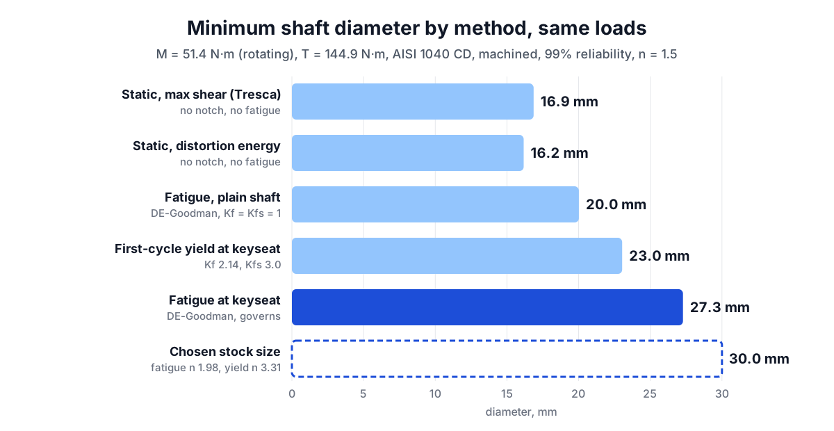
A static distortion-energy calculation with no stress concentration suggests 16.2 mm, little more than half the fatigue answer. Removing the keyseat (Kf = Kfs = 1) brings the fatigue diameter down to 20.0 mm, so the keyseat alone costs more than 7 mm here. Round up to 30 mm, a common bearing bore and stock size. Switch the calculator to "Check a diameter" and enter 30 mm: the fatigue factor of safety is 1.98 and the yield factor is 3.31.
Step 4: stress and twist from torsion alone
The Shaft Torsion Calculator gives the nominal picture for the torque. Enter 144.9 N·m, a 30 mm solid shaft, 0.4 m from the gear to the coupling and the carbon steel preset (G = 79.3 GPa). The nominal shear stress is τ = 16T / (πd³) = 27.3 MPa, and the shaft winds up 0.527° over that length.
The nominal 27.3 MPa looks harmless against a 490 MPa yield strength, but at the keyseat Kfs = 3.0 lifts it to 82.0 MPa, the figure the diameter calculator works with. Twist depends on the shear modulus, which is almost the same for every steel, so a stronger grade would not reduce the 0.527°; only a bigger diameter (J grows with d⁴) or a shorter shaft does.
Step 5: the key, its keyseat and its length
For a 30 mm shaft DIN 6885-1 specifies an 8 × 7 mm parallel key, because 30 mm falls in the "over 22 up to 30 mm" row. The keyseat is t1 = 4.0 mm deep in the shaft and the hub keyway t2 = 3.3 mm. In the Shaft Key Size Calculator enter 30 mm, 144.9 N·m, a key of cold-drawn AISI 1020 (Sy = 390 MPa), 490 MPa for the shaft and hub, n = 2 and a 40 mm hub, and keep the default form A key (round ends).
The torque becomes a force at the shaft surface, F = 2T / d = 2 × 144,900 / 30 = 9,660 N. Shigley section 7-7 checks the key in shear and in crushing on its side faces. In a DIN keyseat only h − t1 = 7 − 4 = 3 mm of the key projects into the hub, so that is the bearing height, not half the key height as in the inch standard:
- shear across the key: L = F·n / (0.577 · Sy · w) = 9,660 × 2 / (0.577 × 390 × 8) = 10.7 mm
- crushing on the hub side: L = F·n / (Sy · (h − t1)) = 9,660 × 2 / (390 × 3) = 16.5 mm
Crushing governs, as it does for standard keys whose own material is the weakest in the joint. A form A key has round ends and bears only on l − b, so it needs l ≥ 16.5 + 8 mm: the calculator gives 25 mm, with factors of 3.17 in shear and 2.06 in crushing. The hub, not strength, sets the final length. The "Key filling the hub" card gives the longest standard key that fits the 40 mm hub: 40 mm, bearing on 32 mm, with a bearing stress of 100.6 MPa and factors of 5.96 in shear and 3.88 in crushing. That key is also shorter than 1.5 shaft diameters (45 mm), the length beyond which Shigley warns that shaft twist loads one end of the key more than the other.
The same method in inch units
Shigley's Example 7-6 is the inch version of step 5: a 1 7/16 in shaft carrying 40 hp at 600 rpm, so T = 63,025 × 40 / 600 = 4,202 lbf·in. ASME B17.1 gives a 3/8 in square key for shafts over 1 3/8 up to 1 3/4 in, half its height deep in shaft and hub. With a key of Sy = 65 kpsi and a design factor of 2.8, shear needs 1.16 in and crushing 1.34 in. These are the calculator's inch defaults.
One edition note for anyone checking against a textbook. The 11th edition of Shigley revised its surface factor constants: for a machined surface ka = 2.00 × Sut^-0.217 (kpsi) instead of the older 2.70 × Sut^-0.265. Run the 10th edition's Example 7-1 (a 1.100 in shaft at a shoulder, Sut = 105 kpsi) and the printed DE-Goodman factor of 1.62 becomes 1.52, because Se drops from 29.3 to 27.1 kpsi.
Mistakes that undersize shafts and keys
- Sizing for torque only. A static distortion-energy size for the torque alone is 15.8 mm in this example. Bending from the gear forces, reversed every revolution, together with the keyseat's stress concentration, takes the fatigue answer to 27.3 mm, about 70% more.
- Putting steady bending in the mean column. On a rotating shaft a steady sideways load is alternating stress. Enter it as Ma.
- Checking only the largest moment. A sharp shoulder fillet (Kt around 2.7) at a smaller moment can govern.
- Stopping at strength. Also check deflection at the gear, slope at the bearings and critical speed.
These numbers are a preliminary design. For lifting equipment, vehicles, pressure equipment or any machine where a broken shaft could hurt someone, have the design checked by a qualified mechanical engineer against the code and the material certificates that apply to it.
Tools for this job
- Shaft Diameter Calculator: the minimum diameter for fatigue and yield at each critical section, or the factors of safety for a size you have.
- Shaft Torsion Calculator: nominal shear stress, twist and stiffness for solid, hollow and stepped shafts.
- Shaft Key Size Calculator: the standard key and keyseat depths for the diameter, and the length for shear and crushing.
- Torque and Power Calculator: torque from kW or hp and rpm, the starting point for every shaft.
- Gear Ratio Calculator: speed and torque on each shaft of a gear train.
- Stress and Strain Calculator: direct stress from axial loads such as helical gear thrust.
Related reading: the torque, horsepower and rpm guide explains the power formulas used in step 1, gear train ratios explained covers why torque grows towards the output shaft, and the bearing L10 life guide picks up the bearing loads from step 2.
Frequently asked questions
Why do shafts usually break at the keyseat or shoulder rather than in the middle of a plain length?
Fatigue cracks start where the local stress is highest, and a keyseat or a sharp shoulder fillet multiplies the nominal stress by two to three. The gear seat is also often where the bending moment peaks, so stress concentration and the largest moment coincide at the same spot.
Should the design factor for the key be higher than for the shaft?
Not necessarily. The key is meant to be the weakest link, so an overload shears a cheap part; that is why it is made from a softer steel. What matters more is that the key length fills most of the hub and that you used the peak torque, because a short or loose key frets and wears its keyseat.
Can I use the same method for an aluminium shaft?
The equations for stress and twist are the same, but aluminium alloys have no endurance limit, so the 0.5 × Sut rule and the steel Marin factors do not apply. Use a fatigue strength for your number of cycles from the alloy's data and enter it as Se, and expect about three times the twist of a steel shaft of the same size, because G is about a third of steel's.
When is a key not the right shaft-hub connection?
When the required key is longer than the hub or than about 1.5 shaft diameters, when the torque reverses often enough to work a key loose, or when the hub must be positioned at any angle. Splines, shrink or press fits and keyless locking bushes carry more torque in the same length; the ISO fits guide covers the interference fits behind press-fitted hubs.
Sources and further reading
- Shigley's Mechanical Engineering Design, 11th edition, Budynas and Nisbett, McGraw-Hill. Chapter 6 (Marin factors, Table 6-2), chapter 7 (Eq. 7-8, Table 7-1, keys in section 7-7, Examples 7-1 and 7-6) and Table A-20.
- B17.1 Keys and Keyseats, ASME. Key size versus shaft diameter for inch shafts (1967, stabilised 2023).
- DIN 6885-1:2021-11 Drive type fastenings without taper action, parallel keys, keyways - Deep pattern - Part 1: Dimensions, tolerances, mass, DIN Media. Metric key sizes, keyseat depths and lengths (edition 2021-11).
- Torsion: Summary and Further Reading, TU Delft OpenCourseWare. Torsion formula and segmented shafts.
Open the Shaft Diameter Calculator
More Mechanical
Every tool in the Mechanical section, free and in your browser.
- Torque and Power Calculator
- Gear Ratio Calculator
- Pulley and Belt Calculator
- Bolt Torque Calculator
- Spring Calculator
- Stress and Strain Calculator
- Bearing Life Calculator
- Hydraulic Cylinder Calculator
- Tap Drill Size Calculator
- Speeds and Feeds Calculator
- ISO Fits & Tolerances Calculator
- Bolt Circle Calculator
- Shaft Torsion Calculator
- Shaft Diameter Calculator
- Shaft Key Size Calculator