
Static vs Dynamic Compression Ratio: How to Calculate Both
Every volume in the clearance space, the sign convention for dished and domed pistons, how intake closing sets dynamic compression, and what pump fuel tolerates.
By Redbison Dev · · Updated · 11 min read

Compression ratio decides how hard an engine squeezes its charge before the spark, and with it how much power and efficiency it makes and how close it runs to detonation. The number is simple to define and easy to get wrong, because the small space above the piston at top dead centre is made of four or five separate pieces, and each one has to be measured or calculated and added with the right sign. Then there is the second number, dynamic compression, which accounts for the camshaft and explains why two engines with the same static ratio can need very different fuel. This post works through both with a small block Chevrolet 350 example, using the Compression Ratio Calculator.
The static compression ratio
Static compression ratio is the volume in the cylinder with the piston at bottom dead centre (BDC) divided by the volume with the piston at top dead centre (TDC):
CR = (V_swept + V_clearance) / V_clearance
The swept volume is one cylinder's displacement, (π / 4) x bore² x stroke, explained in the post on engine displacement, bore and stroke. The clearance volume is everything left above the piston crown at TDC. Because the clearance volume sits in the denominator and is small, a change of a few cubic centimetres moves the ratio a long way. That sensitivity is the whole reason engine builders measure it so carefully.
The pieces of the clearance volume
The clearance volume is a stack of four contributions, each with its own source:
V_clearance = V_chamber + V_gasket + V_deck + V_piston
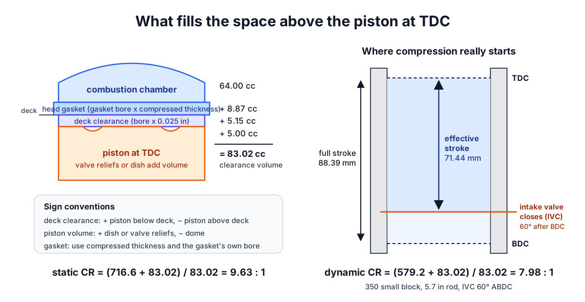
Combustion chamber. The volume of the recess in the cylinder head, with valves and spark plug fitted. It is quoted by the head maker and best checked by filling the chamber with liquid from a burette against a clear plate. Small block Chevrolet heads commonly come in sizes such as 64 cc and 76 cc.
Head gasket. A thin disc whose diameter is the gasket's bore (usually slightly larger than the cylinder bore) and whose thickness is the compressed thickness, not the thickness out of the packet:
V_gasket = (π / 4) x gasket_bore² x compressed_thickness
Deck clearance. The distance between the piston crown and the top of the block (the deck) at TDC. The space is a disc of cylinder bore diameter:
V_deck = (π / 4) x bore² x deck_clearance
The sign convention matters here. In the calculator a positive deck clearance means the piston sits below the deck at TDC, which adds volume. A negative value means the piston pokes above the deck, which happens on some zero-deck or high-compression builds, and that subtracts volume.
Piston volume. The crown shape. A dish or the valve reliefs cut into a flat-top piston leave extra space, so they add volume and are entered as a positive number. A dome fills part of the chamber, so it is entered as a negative number. Piston makers quote this figure in cc; check whether their number for a domed piston already nets off its valve reliefs.
Worked example: a 350 small block
Take a 4.000 in bore, 3.480 in stroke, 64 cc heads, a gasket with a 4.100 in bore and 0.041 in compressed thickness, the piston 0.025 in below the deck, and flat-top pistons with 5 cc of valve reliefs:
V_swept   = (π / 4) x 4.000² x 3.480         = 716.6 cc
V_gasket  = (π / 4) x 4.100² x 0.041         =   8.87 cc
V_deck    = (π / 4) x 4.000² x 0.025         =   5.15 cc
V_piston  = +5 cc (reliefs)                  =   5.00 cc
V_chamber                                    =  64.00 cc
V_clearance = 64 + 8.87 + 5.15 + 5           =  83.02 cc

CR = (716.6 + 83.02) / 83.02                 =   9.63 : 1
Now change one thing at a time to see the sensitivity:
- 76 cc heads instead of 64: clearance 95.02 cc, CR 8.54:1. Twelve cc of chamber cost more than a full point.
- Zero deck (piston flush with the deck): CR 10.20:1. Machining 0.025 in off the deck added more than half a point.
- A 6 cc dome in place of the 5 cc reliefs: CR 10.95:1.
- A thinner 0.027 in gasket: CR 9.96:1.
The calculator also runs the formula backwards. To reach 10.5:1 with everything else in the example unchanged, the chamber would need to be 56.4 cc. To get 9.5:1, 65.3 cc.
Dynamic compression and the intake valve
Static compression assumes the charge is trapped the moment the piston leaves BDC. It is not. The intake valve stays open after BDC, often by 50 to 80 degrees of crank rotation on a performance cam, to let the inrushing air keep filling the cylinder at high rpm. Until it closes, the rising piston pushes some charge back into the intake port, and no compression happens. Real compression only starts at intake valve closing (IVC).
Dynamic compression ratio uses the piston's distance from TDC at IVC in place of the full stroke. Where the piston is at a given crank angle comes from slider-crank geometry, which needs the connecting rod length l as well as the crank radius r (half the stroke):
x(θ) = r + l − ( r cos θ + √( l² − r² sin² θ ) )
x is the distance below TDC at crank angle θ, measured from TDC. IVC at 60 degrees after BDC is θ = 240 degrees. For the 350 with a 5.7 in rod:
effective stroke  = x(240°)                   = 71.44 mm (2.813 in)
effective swept   = (π / 4) x 101.6² x 71.44 = 579.2 cc
DCR = (579.2 + 83.02) / 83.02                 = 7.98 : 1
The same engine with IVC at 70 degrees ABDC drops to 7.39:1, and at 45 degrees rises to 8.70:1. A longer 6.0 in rod changes the 60 degree result only a little, to 7.95:1, because rod length mainly shifts where the piston sits partway through the stroke.
Which IVC figure to use. Cam cards give valve events at different lift points. The most common is the 0.050 in lift figure, which closes earlier than the valve actually seats. Dynamic compression should use the closing point at or near the seat, often called seat timing or advertised duration. If you only have the 0.050 in figure, adding about 15 degrees is a common rule of thumb for a hydraulic flat-tappet or roller cam, but it is an approximation, and the cam maker's advertised figure is better when you can get it.
What ratios will pump fuel tolerate?
There is no single safe number, because detonation depends on chamber design, cylinder head material, cooling, ignition timing, air temperature and the fuel itself. A few patterns hold:
- Modern engines with compact chambers, aluminium heads and knock sensors run static ratios of 10:1 to beyond 12:1 on pump fuel, and direct injection lets some go higher because the fuel spray cools the charge.
- Older two-valve pushrod engines with iron heads and open chambers are less tolerant. For those, engine builders often aim for a dynamic ratio around 8:1 to 8.5:1 on premium pump fuel. That band is experience, not a law; treat it as a starting point.
- A big cam and a high static ratio go together. A long-duration cam closes the intake late, which bleeds off dynamic compression at low rpm, so the static ratio has to rise to keep low-speed torque. That is why the cam choice and the piston choice are made together.
Forced induction changes the picture entirely: boost raises the pressure at IVC, so the effective compression is much higher than either ratio suggests, and boosted engines usually run lower static ratios.
Common mistakes
- Using the uncompressed gasket thickness. The packet thickness can be several thousandths more than the installed figure.
- Getting the deck or dome sign backwards. Piston below the deck adds volume. A dome removes it. A sign error here can move the ratio by more than a point.
- Using the cylinder bore for the gasket volume. The gasket's own bore is usually larger, and the difference is worth roughly half a cc on a 350.
- Dynamic compression from 0.050 in timing. That figure closes too early and overstates DCR.
- Trusting catalogue chamber volumes on used or reworked heads. Valve jobs and port work change the volume. Measure.
Where the simple model stops
Dynamic compression is a geometric index, not a measurement of cylinder pressure. It ignores the fact that at high rpm the inrushing charge keeps filling the cylinder after BDC, which is exactly why late intake closing helps power up there, and it ignores heat, valve overlap and exhaust scavenging. Two engines with the same DCR can behave differently on the same fuel. A cranking compression test with a gauge gives a real-world check, though gauges differ and the result depends on cranking speed and how open the throttle is.
Treat the calculator's numbers as planning estimates to compare options and get close to a target before parts are ordered. Final decisions on fuel and timing belong to measured volumes, the cam maker's advice and careful tuning. For the power side of the same engine, see the Horsepower Calculator and the post on estimating horsepower from quarter-mile times. For gearing it to the road, see road speed from rpm, gear ratio and tyre size and the Gear Speed Calculator.
Frequently asked questions
What compression ratio does a 350 small block get with 76 cc heads?
With a 4.000 in bore, 3.480 in stroke, a 0.041 in gasket of 4.100 in bore, the piston 0.025 in below the deck and 5 cc of valve reliefs, a 350 small block makes 8.54:1 with 76 cc heads. The same engine with 64 cc heads makes 9.63:1, so twelve cc of chamber volume cost more than a full point of compression.
How does the camshaft affect compression?
The camshaft sets intake valve closing, and real compression only starts once the intake valve closes after bottom dead centre. A long-duration cam closes the intake late, which bleeds off dynamic compression at low rpm. For a 350 example, closing at 60 degrees ABDC gives 7.98:1 dynamic, while 70 degrees drops it to 7.39:1, which is why cam and piston are chosen together.
Does connecting rod length change dynamic compression ratio?
Only a little. In a 350 small block example with intake valve closing at 60 degrees after bottom dead centre, a 5.7 in rod gives a dynamic compression ratio of 7.98:1 and a longer 6.0 in rod gives 7.95:1. Rod length mainly shifts where the piston sits partway through the stroke, so the cam timing matters far more.
What are common mistakes when calculating compression ratio?
Common compression ratio mistakes include using the uncompressed head gasket thickness, getting the deck clearance or dome sign backwards, using the cylinder bore instead of the gasket's larger bore for gasket volume, calculating dynamic compression from 0.050 in cam timing, and trusting catalogue chamber volumes on used or reworked heads. A sign error alone can move the ratio by more than a point.
How does turbocharging affect compression ratio?
Forced induction raises the pressure in the cylinder at intake valve closing, so the effective compression is much higher than either the static or dynamic ratio suggests. That is why boosted engines usually run lower static compression ratios.
Sources and further reading
- Compression ratio, Wikipedia. Static and dynamic compression ratio.
- Internal Combustion Engines (course 2.61), MIT OpenCourseWare. MIT's graduate course on engine fundamentals.
- Selecting the Right Octane Fuel, US Department of Energy. Why higher compression and boost need higher octane fuel.
Open the Compression Ratio Calculator
More Automotive
Every tool in the Automotive section, free and in your browser.